Eliminate Hand Soldering of PC104 Connectors
We have developed a family of connectors with integral solder which allows
all pins to be soldered at one time using standard reflow processes (IR,
Convection).
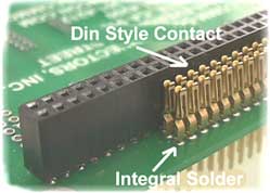
Integral Solder Matrix
Our PC/104 and PC/104-Plus connectors are available with integral solder. This allows you to reflow solder all of the pins at one time. Some soldering systems provide solder on only one side of the board. This can create potentially weak joints because the mechanical stress is pivoted on this one side. Hand soldering can sometimes result in solder getting onto the gold mating surface, thus requiring the connector to be replaced.
Our integral solder system provides a full solder joint on both sides of the board. Our solder system should provide joints which meet IPC-A-610 Class 3 (www.ipc.org) Our solder joints can be easily inspected both top side and bottom side. Our system also elimates the chance of getting solder on the gold mating surfaces.
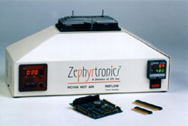
Hot Air Reflow System
Our connectors can be soldered using either standard reflow
processes (IR, Convection) or a ZT-6 AirFountain system. The ZT-6 AirFountain
system uses directed hot air which heats the connectors safely without
damage to surrounding components. This low cost table top machine will
reflow solder all pins in a single step. The machine also provides the
ability to easily remove the connectors for rework.
High Reliability Contact - PC/104 .100" pitch Connector
|
We designed our PC/104 connector
using a DIN style contact. The DIN "spring leaf" contact
has been a proven high reliability design used in DIN back plane
connectors for many years. It provides a superior contact over
the typical "fork" designs used by other suppliers.
The DIN contact is moreforgiving to stress caused by mis-mating.
You can feel the difference with our PC/104 .100" pitch connector.
|
|
Processing Connectors with Integral Solder
1.1 Contents
| The purpose of this information is to provide recommended soldering specifications and procedures for use of our connectors with integral solder. These are recommended procedures, only. Specific soldering technieques and temperatures will be dependent on the particular application, materials and equipment. |   |
2.1 PCB Hole Size
The solder matrix for .100" pin spacing (PC/104 J1 & J2) was designed for use on a .044" diameter hole in a .062" thick PCB. The solder matrix for the 2mm pin spacing (PC/104 J3) was designed for use on a .031" to .032" diameter hole in a .062" thick PCB. There should be sufficient solder to accommodate slight variations to the hole diamter or board thickness.
2.2 Type of Flux
Flux must be applied. We recommend that you test your current flux to see if it provides satisfactory results. We suggest Alpha NR200, NR310M or the Zephyrtronics ZRF-2000. The NR310M is a more aggressive version of the NR200. All of these fluxes are alcohol based no clean and are water soluble. If you required a water based flux for use in your reflow overn, we suggest Kester #2222 which is a VOC free water soluble flux. The Kester #222 is formulated to provide maximum capillary wetting action which is well suited for multi-layer boards. If the connectors are soldered after the rest of the boards have been soldered and cleaned, then you may want to use a no clean flux. You can get more information on fluxes by visiting the Alpha (www.alphametals.com) and Kester (www.kester.com) web sites.
2.2A Tacky Flux
If you have chip components adjacent to the connector, the alcohol based fluxes may wick to these adjacent solder joints and cause solder slump. In this situation, we suggest the us of a tacky flux formulation. This can be supplied in the area directly under the connector and will reduce the chance for wicking and solder slump.
2.3 Flux Application
With the liquid fluxes we recommend application to both the top and bottom side of the board. With the alcohol based fluxes this may be done after the connnectors are inserted into the board. The alcohol based flux easily wicks into the middle of the connector. A plastic flux bottle with a needle dispenser works well. Apply a liberal amount of solder flux. With water based fluxes, apply the flux to the top side of the board, then insert the connector. then apply flux to the bottom side. if you are using tacky flux, apply it to the top side of the board before inserting the connector. (Flux bottle information available at the bottom on this page).
2.4 Temperature Profile - Oven Reflow Processes
We use 63/67 solder which should reflow well using most
standard temperature profiles as long as your oven has bottom side heating.
The following is some basic solder profile information.
Solder Ramp: Room temp. to 140-160°C at a rate of 60-120°C / minute.
Solder Dwell: Time above liequidus should be 30-45 seconds. Exposure to ramp and heat of 160°C-225°C for 60-90 seconds should provide proper reflow.
Solder Liquidus: 183°C (361°F).
Cool Down: Rapid cool down provides the stronget solder joints - prevents lead from sweating out.
2.5 Temperature Profile - Zephyrtronics Air Fountain - click for further information
Zephyrtronics manufactures reflow machines specifically designed for PC/104 and PC/104-Plus. If you using the Zephyrtronics AirFountain reflow system a temperature setting of around 490°F (254°C) works well. The time required to provide good solder fillets will vary depending on the flux used, ambient air temperature/humidity, the particular connector used and the desired fillet quality.
PC/104 Connectors (.100" pitch using .025" square pins):
For the PC/104 connectors using Alpha NR200 or NR310M you should be able to obtain IPC-610-A Class 3 joints in as little as 45 seconds. If the boards are allowed to heat for 90-120 seconds then you will obtain increased fillets fills and reduce the chance for defects. The NR310M provides slightly better results but requires slightly more time then the NR200. We recommend that you leave the connector in heat for at least 15 seconds aftr you see the solder matrix melt and start to wick. We get good results by leaving the connector in heat for 30 to 45 seconds after the solder has reflowed. This give the solder more time to draw across the bottom side pad. Remember that the alcohol in the flux will draw away heat as the alcohol evaporates so the more flux the longer the time to achieve temperature and reflow.
PC/104-Plus Connectors (2mm pitch using .020" square pin):
The PC/104-Plus connectors require slightly more than the PC/104. These 2mm (0.79") pitch connectors will require more attention in processing than the PC/104 due to the close pitch and limited pad sizes. We recommend use of NR310M for this connector in order to improve the draw down of the solder through the hole. We have found that processing times of 120 to 180 seconds works well. This should result in the connector being exposed to heat for around 45 seconds after the soldered has reflowed. Your soldering time should be based on the time after the solder has melted. Remember that the alcohol in the flux will draw away heat as the alcohol evaporates so the more flux, the longer the time to achieve temperature and reflow.
2.6 Solder Balls
Due to the design of the solder matrix, it is possible to obtain solder balls on the top of side of the board. There are many factors which can influence these results: flux type, hole size, solder mask material, process temperature, etc. The IPC-610-A Class 3 standard does allow for solder balls. These solder balls must be 0.13mm in diameter or less. They should be no closer than 0.13mm distance from the lands or traces unless they are attached to the trace. If solder balls are a concern, we recommend cleaning of the boards. However, we also recommend that you conduct tests to evaluate your particular process.
2.7 IPC-610-A Class 3
The following is a brief discussion of IPC-610-A. We recommend that you obtain a copy of the following documents from IPC (www.ipc.org) if you have any questions or would like to review the IPC standards: ANSI/IPC-A-610, IPC-QE-615, DRM-40.
The IPC stanard has 4 criteria: Target Condition, Minimum Acceptable Condition, Non-conforming Process Indicator, Non-conforming Process Indicator: a condition which does not affect the form, fit or function of a product. Non-Conforming Defect: is a condition that the manufacturer shall rework, repair or scrap.
The IPC document defines different standards based on whether the joint is on thePrimary Side or Secondary Side of the board.
Primary Side: The side of the thru hole assembly containing the most component bodies or the solder destination side (typically) called the top side).
Secondary Side: The opposite side to the Primary side or the solder or source side (typically called the bottom side). Because our solder matrix is placed on the top side of the board, we consider the top side of the board as the Secondary side and the bottom side of the board as the Primary side. This makes more sense in terms of evaluating the solder joints.
Minimum Acceptable Conditions for IPC 610-A Class 3
Per IPC 610A standard a primary side (bottom side) wetting
minimum requirement is 270° . The minimum vertical solder joint fill
requirement is 75%. The secondary side (top side) wetting minimum is 330°
or 11/12. The minimum acceptable land coverage on the primary side (bottom
side) is 0%. The mimimum acceptable land coverage on the secondary side
(top side) is 75%.
Flux Application & Cleaning Supplies
This information is provided for your convenience:
Kahnetics Flux Bottle: KDS-5200LL-3
If you are searching for a flux dispensing bottle you can purchase the
Kahnetics Flux Bottle by visiting the Marshall web site at www.marshall.com/dynamic/pdpage?mi=1230887.
Chemtronics Flux-Off: ES1692
No Clean flux Remover, nonflamable, CFC-free, dries fast, leaves no residue.
This is available at Marshalls web site at www.marshall.com/dynamic/pdpage?mi=205391842
Chemtronics Flux-Off: EX7200
Flux Remover, nonflammable, regular strength, dries fast, leaves no residue.
This is available at Marshalls web site at www.marshall.com/dynamic/pdpage?mi=995957045.
You can visit Chemtronics web site at www.chemtronics.com
for further information on their products.
|
Still
looking – can’t find what you want? |
