| CMM Micro-Connector |
|
FEMALE CRIMP WITH CAVITIES FOR SPECIAL CONTACTS 222 SERIES
Package Outline Drawing
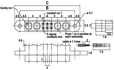
Dimensions : mm
| Dimensions | |
| A | 2mm x (number of contacts per row - 1) |
| B | A + (number of cavities x 4) + 7mm |
| C | B + 5mm |
| Example 222SG 06 M11-22 | |
| A = 2 x (3-1) | A = 4 |
| B = 4 + (4x4) + 7 | B = 27 |
| C = 27 + 5mm | C = 32 |
|
Contact (l)
|
AWG
|
|
(SG) C12468-B
|
24-28
|
|
(C) C13064-P
|
22
|
Select here for special Signal and Coax contacts/pcb layout or Signal and High Power contacts/pcb layout.
For special contacts only housing select here.
| Characteristics | ||
| All contacts |
3 A max @ 25ºC |
|
| 2.2 A max @ 85°C | ||
| Working voltage (sea level) | 240V DC | |
| Proof voltage | 360V DC | |
| Contact resistance (initially) | max 10mW | |
| Insulation resistance |
1 000 M W min |
|
| Mechanical operations | 500 cycles min | |
| Contact insertion and withdrawal force | 2 N max, 0.2 min | |
| Contact retention in insulator | 10 N min | |
| Environmental/Materials | ||
| Insulator | Fibreglass filled thermoplastic UL94VO | |
| Contacts | Male: Tin plated copper alloy, hard acid gold plated | |
|
Female: |
Gold or tin-plated copper alloy socket |
|
| Fixing Hardware | Latch: Beryllium copper alloy socket | |
| Jackscrew: stainless steel CMM 300 series | ||
| Operating Temperature | from -55°C to + 125°C (IEC 68-1) | |
| from -67°F to 257°F | ||
| Complies with vapour phase and infrared techniques | ||
| Vibration severity | 0.75mm, 10 g RMS 6 hours long random with superimposed sinusoid. No imtermittancies measured when using an H.S.L.I (High Speed Logic Interrupt) detector with a trip threshold of 2 ns | |
| Shock severity | 100 g for 6 ms | |
| Resistance | HcFc 141 bMGX (ATOCHEM) solvent | |
Part Numbering System
221l nn Fxx - n©
- u
nn : number of contacts
xx : fixing select here for details
n : Number of cavities for special contacts
(Pin 1 side of L. F. contacts)
© : Number of cavities for special contacts
(other end)
u : Power/coax contacts PN° when all
cavities loaded
![]()